Site pages
Current course
Participants
General
MODULE 1. Analysis of Statically Determinate Beams
MODULE 2. Analysis of Statically Indeterminate Beams
MODULE 3. Columns and Struts
MODULE 4. Riveted and Welded Connections
MODULE 5. Stability Analysis of Gravity Dams
Keywords
LESSON 14. Displacement Method: Slope Deflection Equation – 4
Introduction 14.1: In this lesson we will learn the steps involved in analyzing frames where joint translations are not restrained. In such cases joint translations are also unknown quantities. In addition to moment equilibrium (as discussed lesson 13), additional equations based on shear force in the member are formed. Obtained equations are then solved all the unknowns (rotations are translations). The method is illustrated via the following example.
14.1 Example
Draw the bending moment diagram for the follwing frame. EI is constant for all members.
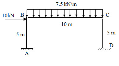
Fig.14.1
Step 1: Fixed end Moments
\[M{}_{FBC} =-{{7.5 \times {{10}^2}} \over {12}} =-62.5{\rm{kNm}}\] ; \[M{}_{FCB} = {{7.5 \times {{10}^2}} \over {12}} = 62.5{\rm{kNm}}\]
\[M{}_{FAB} = M{}_{FBA} = M{}_{FCD} = M{}_{FDC} = 0\]
Step 2: Slope-Deflection Equaitons
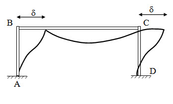
Fig.14.2
Since A and D are fixed ends, θA = θD = 0
Since axial deformation is neglected, δB = δC = δ
For span AB,
\[{M_{AB}} = {M_{FAB}} + {{2EI} \over {{L_{AB}}}}\left( {2{\theta _A} + {\theta _B} - {{3\delta } \over {{L_{AB}}}}} \right) = 0.4EI{\theta _B} - 0.24EI\delta \] (14.1)
\[{M_{BA}} = {M_{FBA}} + {{2EI} \over {{L_{AB}}}}\left( {{\theta _A} + 2{\theta _B} - {{3\delta } \over {{L_{AB}}}}} \right) = 0.8EI{\theta _B} - 0.24EI\delta \] (14.2)
For span BC,
\[{M_{BC}} = {M_{FBC}} + {{2EI} \over {{L_{BC}}}}\left( {2{\theta _B} + {\theta _C} - {{3\delta } \over {{L_{BC}}}}} \right) =-62.5 + 0.2EI\left( {2{\theta _B} + {\theta _C}} \right)\] (14.3)
\[{M_{CB}} = {M_{FCB}} + {{2EI} \over {{L_{BC}}}}\left( {2{\theta _C} + {\theta _B} - {{3\delta } \over {{L_{BC}}}}} \right) = 62.5 + 0.2EI\left( {{\theta _B} + 2{\theta _C}} \right)\] (14.4)
For span CD,
\[{M_{CD}} = {M_{FCD}} + {{2EI} \over {{L_{CD}}}}\left( {2{\theta _C} + {\theta _D} - {{3\delta } \over {{L_{CD}}}}} \right) = 0.8EI{\theta _C} - 0.24EI\delta \] (14.5)
\[{M_{DC}} = {M_{FDC}} + {{2EI} \over {{L_{CD}}}}\left( {{\theta _C} + 2{\theta _D} - {{3\delta } \over {{L_{CD}}}}} \right) = 0.4EI{\theta _C} - 0.24EI\delta \] (14.6)
Step 3: Equilibrium Equaitons
At B,
\[{M_{BA}} + {M_{BC}} = 0 \Rightarrow 0.8EI{\theta _B} - 0.24EI\delta-62.5+0.2EI\left( {2{\theta _B} + {\theta _C}} \right) = 0\]
\[\Rightarrow 1.2EI{\theta _B} + 0.2EI{\theta _C}-0.24EI\delta-62.5=0\] (14.7)
At C,
\[{M_{CB}} + {M_{CD}} = 0 \Rightarrow 62.5 + 0.2EI\left( {{\theta _B} + 2{\theta _C}} \right) + 0.8EI{\theta _C}--0.24EI\delta= 0\]
\[\Rightarrow 0.2EI{\theta _B} + 1.2EI{\theta _C}-0.24EI\delta+62.5=0\] (14.8)
Step 3: Additional Shear Equation
Free body diagram of each member are shown bellow.
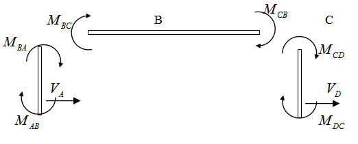
Fig.14.3
Summation of force in horizontal direction is zero \[ \Rightarrow \sum {{F_x} = 0}\]
Here, horizontal forces are, external horizontal force of 10 kN and shear forces VA and VB respectively at support A and D.
From the above FBD, VA and VB may be expressed as,
\[{V_A} = {{{M_{AB}} + {M_{BA}}} \over {{L_{AB}}}} = {{0.4EI{\theta _B} - 0.24EI\delta+0.8EI{\theta _B}-0.24EI\delta }\over 5}={{1.2EI{\theta _B}-0.48EI\delta } \over 5}\]
\[{V_B} = {{{M_{AB}} + {M_{BA}}} \over {{L_{AB}}}} = {{0.8EI{\theta _C} - 0.24EI\delta+0.4EI{\theta _C}-0.24EI\delta }\over 5}={{1.2EI{\theta _C}-0.48EI\delta } \over 5}\]
Now,
\[\sum {{F_x} = 0}\Rightarrow {V_A} + {V_B} + 10 = 0\]
\[{{1.2EI{\theta _B} - 0.48EI\delta } \over 5} + {{1.2EI{\theta _C} - 0.48EI\delta } \over 5} + 10 = 0\]
\[1.2EI{\theta _B} + 1.2EI{\theta _C}-0.96EI\delta+50= 0\] (14.9)
Solving equations (7) – (9), we have,
\[{\theta _B} = {{78.125} \over {EI}}\] , \[{\theta _C} =-{{46.875} \over {EI}}\] , \[\delta=-{{91.1458} \over {EI}}\]
Step 4: End Moment calculation
Substituting, θB, θC and δ into equations (1) – (6), we have,
\[{M_{AB}} = 0.4EI{\theta _B} - 0.24EI\delta= 9.375{\rm{ kNm}}\]
\[{M_{BA}} = 0.8EI{\theta _B} - 0.24EI\delta= 40.625{\rm{ kNm}}\]
\[{M_{BC}} =-62.5 + 0.2EI\left( {2{\theta _B} + {\theta _C}} \right) =-40.625{\rm{kNm}}\]
\[{M_{CB}} = 62.5 + 0.2EI\left( {{\theta _B} + 2{\theta _C}} \right) =59.375{\rm{ kNm}}\]
\[{M_{CD}} = 0.8EI{\theta _C} - 0.24EI\delta=-59.375{\rm{kNm}}\]
\[{M_{DC}} = 0.4EI{\theta _C} - 0.24EI\delta=-40.625{\rm{ kNm}}\]
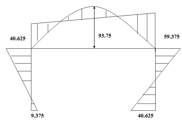
Fig. 14.4. Bending Moment Diagram.
Suggested Readings
Hbbeler, R. C. (2002). Structural Analysis, Pearson Education (Singapore) Pte. Ltd.,Delhi.
Jain, A.K., Punmia, B.C., Jain, A.K., (2004). Theory of Structures. Twelfth Edition, Laxmi Publications.
Menon, D., (2008), Structural Analysis, Narosa Publishing House Pvt. Ltd., New Delhi.
Hsieh, Y.Y., (1987), Elementry Theory of Structures , Third Ddition, Prentrice Hall.
Last modified: Wednesday, 18 September 2013, 7:19 AM